
General information
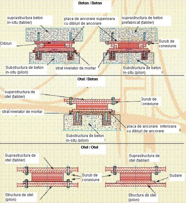
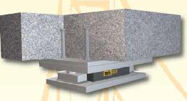
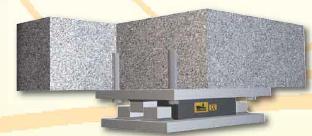
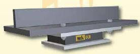
The limiting structures are steel components that enclose hardened elastomeric supports. They transmit the horizontal load from the superstructure to the substructure.
Among the current horizontal loads are the wind, the resetting forces from translation, breaking, friction and centrifugal forces at curved bridges.
Depending on the type of limitation, the brackets on the top and bottom bracket may transmit particular loads such as:
Fx = longitudinal force (kN)
Fy = transverse forces (kN)
Vx = displacement in direction x (mm)
Vy = alignment in the y direction (mm)
Note: In the practical application “x” is always the main direction (longitudinal direction) of the bridges.
The limiting structures are divided into Group I and Group II. Group I (sliding pair – steel / steel) are manufactured for ≤ 50 mm travel (SLS) or track bridges with a prolonged length of ≤ 25 m. Group II limiting structures (sliding pair – stainless steel / sliding material) are applicable to structures where Group I can not be used.
The criteria for sizing and designing the containment structures can be found in DIN 4141 Part 13 as well as in EN 1337 Part 8.
The dimensioning of the limiting structures is based on the available structural values. Limiting structures are adapted to the site (site conditions, plant height, etc.)
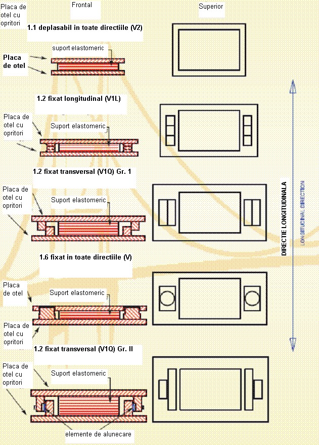
The following different types of structures are the most common:
- longitudinally fastened – the support is fixed in the direction of longitudinal construction. The forces in this direction are transmitted.
- fixed transversely – the support is fixed in the direction of cross-construction. The forces in this direction are transmitted.
- fixed in all directions – the support is fixed in the longitudinal and transverse construction directions. Forces in these directions are transmitted.
For the choice of the support plane, that is, the type and position of the limiting structures, it must be taken into account that the bridge or the structure as a whole must be capable of expanding without limitation.
The symbols and numbers of the holders are specified in EN 1337 Part 1 – General Design Rules, to provide clear information on the type of support.